Macro Keyboard Project
Introduction
Welcome to my first personal project! Throughout
this past Winter Break, I have been working through and
developing a USB HID device that acts as a macro keyboard.
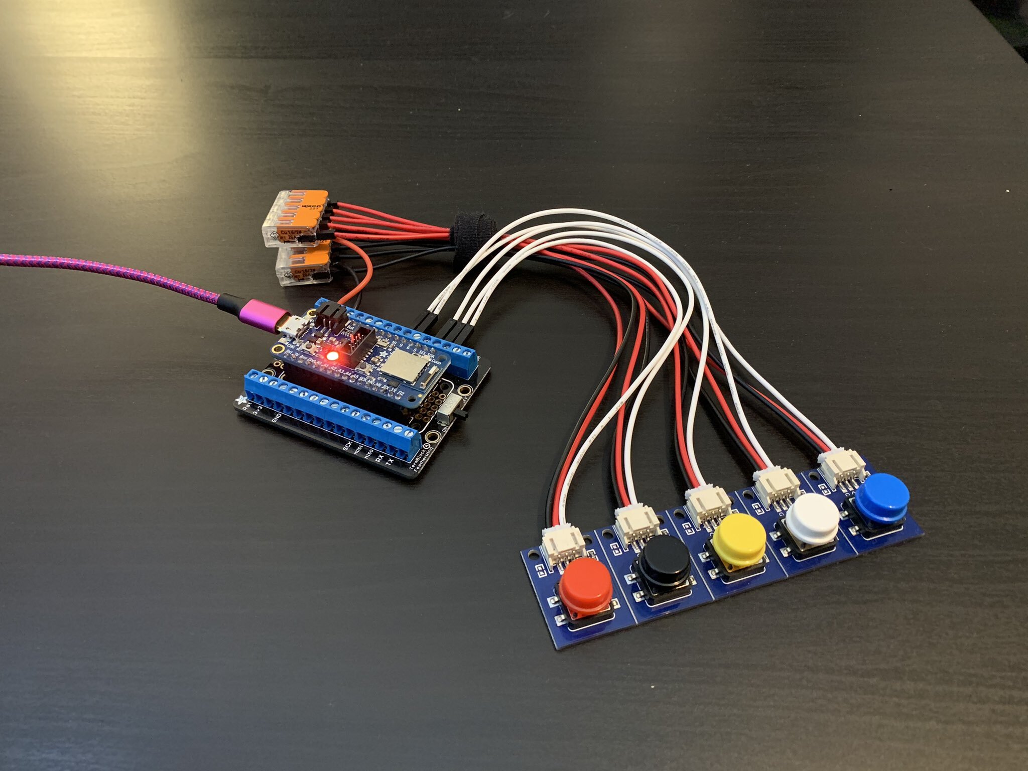
Utilizing CircuitPython on the
Adafruit Feather nrf52840 Express
microcontroller, I was able to
develop such a device. The concept and hardware used in
this project was heavily influenced by
this project by John Park, which was a bluetooth HID keyboard. I was intrigued by the Bluetooth capabilities of the device. However, I encountered
several problems with the libraries necesarry to make the Bluetooth connection. I decided to continue on with the
project without Bluetooth connectivity and just a USB connection. Originally, this project was designed to be a keyboard that can store
and output passwords, essentially acting as an auto-fill that did not require any storage of those passwords online. However, with
how easy it is to view the source code (code.py) file, it just did not seem practical to store sensitive information like that.
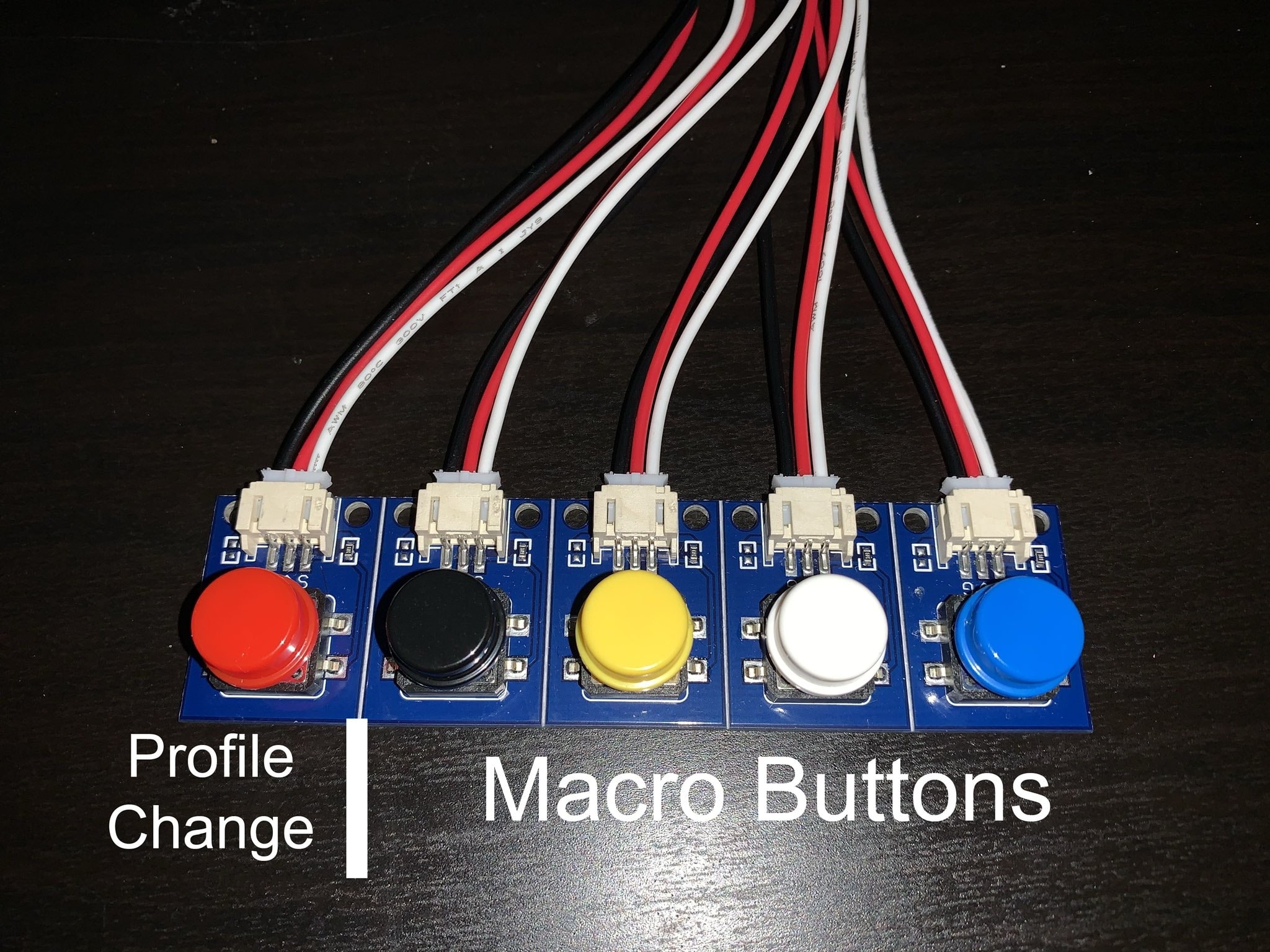
So moving forward, I took into account that fact that with only 5 total buttons available, there should be a way to add more usabilityto the device.
I decided to opt for a multi-profile approach, where one button controls the changing of profiles and the rest handling the outputs.
Overview
This device works as a fully-customizable multi-profile 4-Key macro keyboard, with CircuitPython being behind the code to achieve this.
CircuitPython is an Adafruit supported derivative of MicroPython, which is
essentially an optimized version of Python that runs on a microcontroller. Each profile is signified by the neopixel LED on the board.
The USB HID library from Adafruit allows us to send keyboard and mouse commands over a USB cable to any compatible device. The 4 rightmost buttons are able to be remapped
by changing the source code. The leftmost button controls the profile switching.
Functionality
As a USB Human Interface Device (HID), the buttons will output strings or keycodes once the board is connected to a computer via USB.
Once connected, the device will show up in the File Explorer as "CIRCUITPY", with the necessary libraries and "code.py", which holds
the code that the board runs. It's important to note that whatever file is named "code.py" is what will be used. Whenever any changes
are saved to that file, the code will be re-run on the board.
At the start of the program, the board will always be set on profile 1. In order to go forward a profile, the user can click the leftmost button. To go back,
that button can be double pressed. The current version of the code has 4 profiles that showcase the capabilities of the device.
As seen in the code
on lines 77-80, each profile is a list with 4 elements for each button. The order of elements in the list corresponds to the order
of buttons from left to right. In the current version of the code, each profile does as follows:
- (Red LED on the board) This profile each button acting as an up, down, left, and right arrow button, respectively.
- (Green LED) This profile showcases the ability to set any of the buttons to act as a space. The rightmost
button is the space and with the rest of the buttons, one can output "Hello world!"
- (Blue LED) This profile showcases the ability to output long strings of text or characters.
- (Yellow LED) This profile showcases the ability to set any of the buttons to a Caps lock
Single clicking then double clicking to move up and down profiles
Using Profile 2 to write "Hello world!"
User Customization
One of the biggest features of this project is the ability for users to be able to change the mapping of the buttons just with
minor changes to the code. As mentioned earlier, lines 77-80 of the code, each profile is neatly laid out as
their own list. The following is a set of instructions on how to add and change profiles.
Adding or Removing Profiles
- Depending on whether you want to add or remove a profile, you first need to change the value of the variable "num_profiles" on line 11
to reflect the desired amount of profiles.
- Changes need to be made to the function "handleColors()" on line 15 so that each profile has a corresponding LED on the board.
elif statements need to be added for a new profile, which follow the command to assign a color to the neopixel RGB LED. The format
to do so is
pixels.fill([RGB value])
RGB values can be found by searching the web, or going to this site.
-
In the top-level script environment, lists of length 4 can be added or removed. It is mandatory that these lists contain elements
that are of type string or Keycode. The documentation for the list of Keycodes can be found
here.
-
On line 82 of the code, the list "macro" must be modified to reflect the amount of profiles, with each of the profile lists in it.
- Save the file.
Conclusion
Overall, this project was a great way to apply my knowledge and experiences from my studies. Being a Computer Engineering student,
I have had experience with high order languages like Python, so writing the code was not a daunting task. However, it is inevitable
that I would run into problems along the way.
The biggest problem that I faced was trying to get the bluetooth functionality to work,
as one of the nRF52840's greatest features is its Bluetooth Low Energy (BLE) capabilities. After meticulously reading through error
messages, I concluded that there was some incompatabilities with the adafruit libraries for BLE. And after trying out all different
kinds of versions, I resorted to sticking with just a USB connection for the device especially since I was not able to access the libraries.
Other small problems included not noticing disconnected wires or forgetting how variables work in python functions. I had not
used Python in quite some time, so the logical and syntax errors were bound to appear. But the rewarding part of the project is
being able to overcome those obstacles and experience the satisfaction of your work functioning correctly.
If I were to redo or continue further on this project, I would look to designing a housing enclosure for the device and switches. Moreover,
I would look into finding a way to rewrite the macro profiles without the need to modify the source code.